This is a Matlab script which interpolates an airfoil geometry and refines it to a desired number of points. Also, the user can:
• Control the distribution of points on the pressure side, leading edge, trailing edge and suction side; • Round the trailing edge; • Close the trailing edge of open trailing edge geometries.
You only need to unzip it in a folder and open the file called “airfoilInterpolation.m”.
Below there is an example showing how the code works using a NACA0012 geometry, which can be downloaded here. A good source where you can find tons of airfoil geometries is airfoiltools.
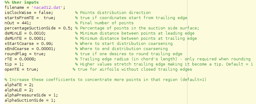
Code inputs for a NACA0012 airfoil
As you can see, there are only a few inputs needed by the code. All of them are detailed next.
• filename – name of the file containing the data; • isClockWise – must be “false” if points are in counter clock wise distribution of “true” if they’re in clock wise distribution; • startsFromTE – must be “false” if points start from the leading edge or “true” if they start from the trailing edge; • nOut – number of points of the outputed geometry; • percentageSuctionSide – percentage of points in the suction side surface of the airfoil; • dsMinLE – minimum distance betweent points at leading edge; • dsMinTE – minimum distance betweent points at trailing edge; • xStartCoarse – where to start coarsening of points distribution; • xEndCoarse – where to end coarsening of points distribution; • roundFlag – if the user wants the trailing edge to be rounded, this variable must be set to”true”; • rTE – radius of the rounding arc relative to chord’s length; • openTE – if the geometry have an open trailing edge, this variable must be set to”true”; • tip – controls how stretched the rounded trailing edge is; • alphaTE, alphaLE. alphaPressureSide. alphaSuctionSide – these parameters concentrate points in their respective regions;
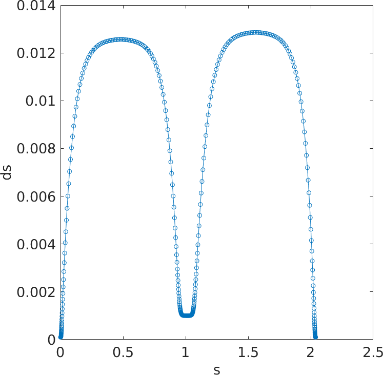
With these inputs, here is the code’s output.
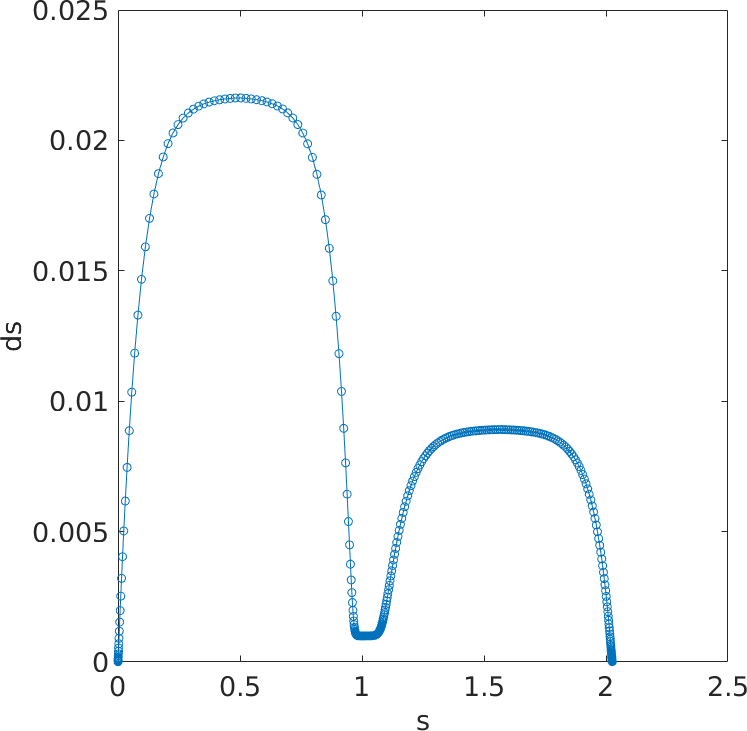
Spacing between surface points
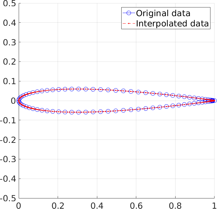
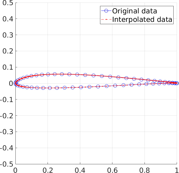
Exported geometry.
A file named “airfoilRefined.dat” is created at the end of the script execution. It has the above points distribution beginning from the trailing edge in counter clock wise orientation with unitary chord’s length.
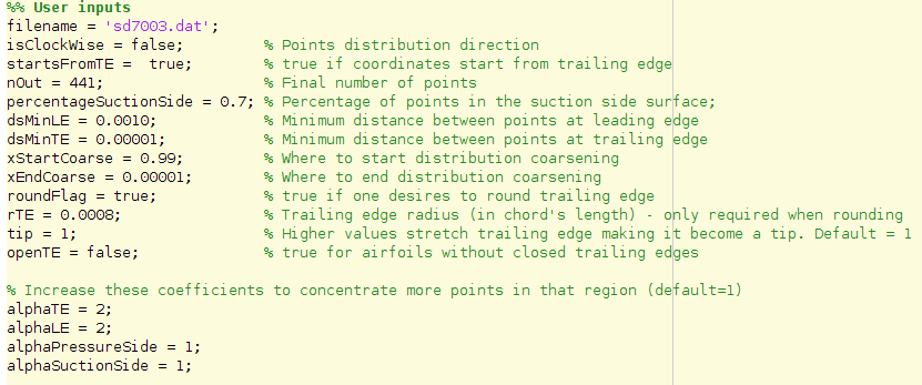
Another example is given but with a SD7003 geometry which can be downoaded here. The inputs used are: